Toll-Free in Philippines: 1 800 8908 8267 | 1 800 1441 0877
International+65 6415 5353

8-Channel Multifunction Ethernet Data Acquisition Module

OM-NET-1608

Ethernet Data Acquisition Module | 8-Channel & Multifunction | OM-NET-1608

See All Models Below
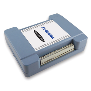
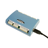
CE
  • 16-Bit High-Speed Ethernet Device
  • Sample Rates up to 250 kS/s
  • 4 Differential (DIFF) or 8 Single-Ended (SE) Analog Inputs
  • Two 16-Bit Analog Outputs
  • Eight Individually-Configurable Digital I/O Lines
  • One 32-Bit Counter Input
  • Includes a Built-In 10/100 BASE-T Auto-Negotiation, High-Speed Communication Port
  • Requires a TCP/IP and UDP Connection to a Network or Computer
  • Includes CAT-6 Ethernet Cable and 5V Power Supply Adaptor (Required to Provide External Power)
  • TracerDAQ® Software Included for Acquiring and Displaying Data and Generating Signals
  • Universal Library Includes Support for Visual Studio® and Visual Studio.NET, Including Examples for Visual C++®, Visual C®, Visual Basic®, and Visual Basic® .NET
  • Comprehensive Drivers for DASYLab® and NI LabVIEW™
  • InstaCal Software Utility for Installing, Calibrating, and Testing
  • Supported Operating Systems: Windows® VISTA/7/8/10 (32- and 64-Bit)
USB, RS232, RS485 and Ethernet Data Acquisition Systems - View related products

Description

The Ethernet-based OM-NET-1608 data acquisition module is a low-cost, high-speed, multifunction I/O device that measures eight analog channels at 250 kS/s aggregate with 16-bit resolution. This device also offers two analog outputs, eight digital I/O channels, and one counter input.

Ethernet Interface
The OM-NET-1608 has a built-in 10/100 BASE-T auto-negotiation, high-speed communication port. The networking protocols are TCP/IP and UDP. Once connected to the network, the device can be remotely accessed and configured through software from anywhere on the network. Only one user at a time can access the OM-NET-1608. Software is required to actively communicate with the OM-NET-1608 over Ethernet. The device does not operate as a stand-alone data logger.

Analog Input
The OM-NET-1608 provides 16-bit analog inputs that are software-selectable as four differential (DIFF) or eight single-ended (SE) inputs. The device supports input ranges of ±10V, ±5V, ±2V, and ±1V that are software-selectable per channel.

Analog Output
The OM-NET-1608 has two 16-bit, software-paced analog outputs that can be updated at a rate of 500 S/s. The output range is fixed at ±10V.

Trigger Input
The OM-NET-1608 has an external digital trigger input. The trigger mode is software-selectable for edge- or level-sensitive mode. You can configure edge-sensitive mode for either rising or falling edge. In level-sensitive mode, you can configure for either high or low level. The default setting at power up is edge-sensitive, rising edge.

Digital I/O
Eight bi-directional digital I/O bits are individually-configurable for input or output. The digital I/O terminals can detect the state of any TTL-level input. You can configure for pull-up (5V) or pull-down (0V) with an onboard jumper.

Counter Input
One 32-bit event counter can count TTL pulses. The counter accept inputs of up to 10 MHz.

Clock I/O
The OM-NET-1608 has one external clock input and one clock output for analog inputs.

Calibration
OM-NET-1608 devices are factory-calibrated. Specifications are guaranteed for one year. For calibration beyond one year, return the device to the factory for recalibration.

Software
The OM-NET-1608 module ships with an impressive array of software, including TracerDAQ®, a full-featured, out-of-the-box data logging, viewing, and analysis application. Driver support and detailed example programs are included for Universal Library programming libraries for Microsoft® Visual Studio® programming languages, and other languages, including DASYLab®, and ULx for NI LabVIEW® (comprehensive library of VIs and example programs compatible with 32-bit and 64-bit LabVIEW 2010 or later) and InstaCal™ installation, calibration and test utility-powerful solutions for programmers and nonprogrammers alike. These modules operate under Microsoft Windows® VISTA/7/8/10 (32- and 64-bit) operating systems.

The OM-NET-1608 data acquisition module is supplied with TracerDAQ software which is a collection of four virtual instrument applications used to graphically display and store input data and generate output signals:

    • Strip Chart—Log and graph values acquire from analog inputs, digital inputs, temperature inputs and counter inputs
    • Oscilloscope—Display values acquired from analog inputs
    • Function Generator—Generate waveforms for analog outputs
    • Rate Generator—Generate waveforms for counter outputs

TracerDAQ PRO is an enhanced version of TracerDAQ and is available as a purchased upgrade (SWD-TRACERDAQ-PRO). A comparison of some of the features included in TracerDAQ vs TracerDAQ PRO is shown on the PDF.

Specifications
ANALOG INPUT
A/D Converter Type:
Successive approximation
ADC Resolution: 16-bits
Number of Channels: 4 differential (DIFF)/8 single-ended (SE), software-selectable
Input Voltage Range: ±10V, ±5V, ±2V, ±1V (software-selectable per channel)
Absolute Max Input Voltage (CHx relative to AGND): ±20V max (power on), ±12V max (power off)
Input Impedance: 1 GΩ (power on), 1200 Ω (power off)
Input Bias Current: ±10 nA
Input Bandwidth (All Input Ranges, Small Signal [-3 dB]): 700 kHz
Input Capacitance: 60 pf
Max Working Voltage (Signal + Common Mode):
    ±10V Range: ±10.2V max relative to AGND
    ±5V Range: ±10.2V max relative to AGND
    ±2V Range: ±9.5V max relative to AGND
    ±1V Range: ±9.0V max relative to AGND
Common Mode Rejection Ratio (fIN = 60 Hz, All Input Ranges): 86 dB
Crosstalk (Adjacent Differential Mode Channels, DC to 10 kHz): -75 dB
Input Coupling: DC
Sample Rate: 0.019 Hz to 250 kHz, software-selectable
Trigger Source: TRIG (see External Trigger)
Sample Clock Source: Internal A/D clock or external A/D clock (AICKI pin)
Internal Sample Clock Stability: ±50 ppm
Internal Sample Clock Timebase: 80 MHz timer with 32-bit period (available frequencies are 80 MHz/integer period)
Throughput: This is the typical throughput when the device and host are both connected by Ethernet to the same local network; the throughput can vary significantly if a wireless connection is involved or data is sent over the internet and is not guaranteed
    Software Paced: 1000 to 5000 S/s typ, on local network
    Hardware Paced: 250 kS/s max
Channel Gain Queue (Up To 8 Elements): Software-selectable channel and range for each queue element
Warm-Up Time: 15 minutes min
Noise Performance: For the peak to peak noise distribution test, a differential input channel is connected to AGND at the input terminal block, and 16384 samples are acquired at the maximum rate available at each setting
Settling Time: Settling time is defined as the accuracy that can be expected after one conversion when switching from a channel with a DC input at one extreme of full scale to another channel with a DC input at the other extreme of full scale; both input channels are configured for the same input range

ANALOG OUTPUT
Number of Channels:
2
Resolution: 16-bits
Output Ranges (Calibrated): ±10V
Output Transient
    Powered On
      Duration:
5 ms
      Amplitude: 2V p-p
    Powered Off
      Duration:
400 ms
      Amplitude: 10V p-p
Differential Non-Linearity (16-bit Monotonic): ±0.35 LSB typ, ±1 LSB max
Output Current (AOUTx Pins): ±3.5 mA max (leave unused AOUTx output channels disconnected)
Output Coupling: DC
Power On and Reset State: DACs cleared to uncalibrated zero-scale: 0V, ±50 mV unless the alarm function is enabled for the output; AOUTx defaults to 0V whenever the device is powered on or a reset command is issued to the device, unless the alarm functionality is enabled for the output
Alarm Functionality: Either or both outputs may be configured to go to defined values when an Ethernet connection with a host is established or lost
Slew Rate: 5V/µs
Throughput (Software Paced): 1000 to 5000 S/s typ, on local network. This is the typical throughput when the device and host are both connected by Ethernet to the same local network. The throughput can vary significantly, and typical throughput is not guaranteed if a wireless connection is involved or data is sent over the internet
Calibrated Absolute Accuracy (Analog Output)
Range:
±10V
Absolute Accuracy: (±18.7 LSB)
CALIBRATED ABSOLUTE ACCURACY COMPONENTS (ANALOG OUTPUT)
Range:
±10V
% of Reading: ± 0.024
Offset: ±2.2 mV
Offset Tempco: 30.1 µV/°C
Gain Tempco: 13.2 ppm of range/°C
Relative Accuracy (Analog Output)
Range:
±10V
Relative Accuracy (INL): ±4.0 LSB typ
ANALOG INPUT/OUTPUT CALIBRATION
Recommended Warm-Up Time:
15 minutes min
Calibration Method: Factory
Calibration Interval: 1 year (factory calibration)

DIGITAL INPUT/OUTPUT
Digital Type:
5V TTL input/advanced BiCMOS output
Number of I/O: 8
Configuration: Independently-configured for input or output
Pull-Up Configuration: All pins pulled up to 5V using 47 K resistors (default); can be changed to pull-down using an internal jumper
Digital I/O Transfer Rate (System-Paced): 100 to 5000 port reads/writes or single bit reads/writes per second typ, on local network. This is the typical throughput when the device and host are both connected by Ethernet to the same local network. The throughput can vary significantly, and typical throughput is not guaranteed if a wireless connection is involved or data is sent over the internet.
Alarm Functionality: Any combination of DIO bits may be configured to become outputs and go to defined values when an ethernet connection with a host is established or lost
Power On and Reset State: All bits are input unless the alarm functionality is enabled for them
Input High Voltage Threshold: 2.0V min
Input High Voltage Limit: 5.5V absolute max
Input Low Voltage Threshold: 0.8V max
Input Low Voltage Limit: -0.5V absolute min, 0V recommended min
Output High Voltage: 3.8V typ at no load, 3.0V min (IOH = -3 mA), 2.0V min (IOH = -32 mA)
Output Low Voltage: 0.15V typ at no load, 0.55V max (IOL = 64 mA)
Power On and Reset State: Input
EXTERNAL TRIGGER
Trigger Source (External Digital):
TRIG
Trigger Mode: Software-selectable edge or level sensitive; user configurable for CMOS-compatible rising or falling edge, high or low level
Trigger Latency: 2 µs + 1 pacer clock cycle max
Trigger Pulse Width: 1 µs min
Input Type: Schmitt trigger, 47 kΩ pull-down to ground
Schmitt Trigger Hysteresis: 1.01V typ, 0.6V min, 1.5V max
Input High Voltage Threshold: 2.43V typ, 1.9V min, 3.1V max
Input High Voltage Limit: 5.5V absolute max
Input Low Voltage Threshold: 1.42V typ, 1.0V min, 2.0V max
Input Low Voltage Limit: -0.5V absolute min, 0V recommended min
EXTERNAL CLOCK INPUT/OUTPUT
Terminal Names:
AICKI, AICKO
Terminal Types
    AICKI:
Input (receives A/D pacer clock from external source)
    AICKO: Output (outputs internal A/D pacer clock)
Input Clock Rate: 250 kHz max
Clock Pulse Width
    AICKI:
1 µs min
    AICKO: 1.8 µs min
Clock Mode: Edge-sensitive, rising
Input Type: Schmitt trigger, 47 kΩ pull-down to ground
Schmitt Trigger Hysteresis: 1.01V typ, 0.6V min, 1.5V max
Input High Voltage Threshold: 2.43V typ, 1.9V min, 3.1V max
Input High Voltage Limit: 5.5V absolute max
Input Low Voltage Threshold: 1.42V typ, 1.0V min, 2.0V max
Input Low Voltage Limit: -0.5V absolute min, 0V recommended min
Output High Voltage: 4.4V min (IOH = -50 µA), 3.80V min (IOH = -8 mA)
Output Low Voltage: 0.1V max (IOL = 50 µA), 0.44V max (IOL = 8 mA)

COUNTER
Pin Name: CTR
Counter Type: Event counter
Number of Channels: 1
Input Type: Schmitt trigger, 47 kΩ pull-down to ground
Input Source: CTR screw terminal
Resolution: 32-bits
Schmitt Trigger Hysteresis: 1.01V typ, 0.6V min, 1.5V max
Input High Voltage Threshold: 2.43V typ, 1.9V min, 3.1V max
Input High Voltage Limit: 5.5V absolute max
Input Low Voltage Threshold: 1.42V typ, 1.0V min, 2.0V max
Input Low Voltage Limit: -0.5V absolute min, 0V recommended min
Input Frequency: 10 MHz max
High Pulse Width: 50 ns min
Low Pulse Width: 50 ns min

MEMORY
Data FIFO (Analog Input):
49,152 samples
Non-Volatile Memory: 2048 bytes (768 bytes for calibration, 256 bytes for user, 1024 bytes for network settings)
POWER
External Power Supply:
5V, 1A (via included AC adaptor)
Supply Current (Quiescent Current): 330 mA typ (this is the total quiescent current requirement for the device that includes the LEDs and does not include any potential loading of the digital I/O bits, +VO terminal, or the AOUTX outputs), 710 mA max including all external loading
User Output Voltage Range (Available at +VO Terminal): 4.40V min to 5.25V max, assumes supplied AC adaptor is used
User Output Current (Available at +VO Terminal): 10 mA max
NETWORK
Ethernet Connection
Ethernet Type:
100 Base-TX, 10 Base-T
Communication Rates: 10/100 Mbps, auto-negotiated
Connector: RJ-45, 8 position
Cable Length: 100 meters max
Additional Parameters: HP Auto-MDIX support
NETWORK INTERFACE
Protocols Used:
TCP/IP (IPv4 only), UDP
Network Ports Used: UDP:54211 (discovery), UDP:6234 (bootloader only), TCP:54211 (commands), TCP:54212 (scan data)
Network IP Configuration: DHCP + link-local, DHCP, static, link-local
Network Name: E-1608-xxxxxx, where xxxxxx are the lower 6 digits of the device MAC address
Network Name Publication: By NBNS (responds to b-node broadcasts, therefore only available on the local subnet)
NETWORK FACTORY DEFAULT SETTINGS
Factory Default IP Address:
192.168.0.101
Factory Default Subnet Mask: 255.255.255.0
Factory Default Gateway: 192.168.0.1
Factory Default DHCP Setting: DHCP + link-local enabled
NETWORK SECURITY
Security Implementation:
TCP sockets are not opened unless application sends the correct PIN code (stored in non-volatile memory, may be changed by user, default value 0000)
Number of Concurrent Sessions: 1
Vulnerabilities: TCP sequence number approximation vulnerability
LED DISPLAYS AND THE FACTORY RESET BUTTON
Power LED (Top)
 3.3 V < Vext < 5.9 V:
On
 Vext < 3.3V, Vext > 5.9V: Off (power fault)
Activity LED (Bottom): On when there is a valid host connection and blinks when a command is received or an AInScan is running
ETHERNET CONNECTOR LEDS
Left, Green:
Link/activity indicator; on when there is a valid ethernet link and blinks when network activity is detected
Right, Yellow: Speed indicator; on for 100 Mbps, off for 10 Mbps or no link
Factory Reset Button: Used to reset the network configuration settings to the factory default values

ENVIRONMENTAL
Operating Temperature Range:
0 to 55°C max (32 to 131°F)
Storage Temperature Range: -40 to 85°C max (-40 to 185°F)
Humidity: 0 to 90% RH non-condensing max
SCREW TERMINAL CONNECTORS
Connector Type:
Screw terminal
Wire Gauge Range: 16 AWG to 30 AWG
MECHANICAL
Dimensions:
117.9 L × 82.8 W × 29.0 mm H (4.64 × 3.26 × 1.14")
Weight: 0.4 kg (0.88 lb)

(Specify Model Number)
Part Number/Desc.
Qty
Description
OM-NET-1608
Consult Sales  
Availability: 
 
 
8-channel multifunction ethernet data acquisition module
OM-NET-DINRAILKIT
Consult Sales  
Availability: 
 
 
DIN rail mounting kit for OM-NET-1608
OM-NET-PS
Consult Sales  
Availability: 
 
 
Spare AC power adaptor for OM-NET-1608, 100/240 Vac 50/60 Hz input, 5V output (includes field interchangeable plugs for US, UK, Europe and Australia)
All prices on this site are shown in Philippine Pesos.
Note: Comes complete with 1 m (3.2') CAT-6 ethernet cable, universal AC adaptor, quick start guide, TracerDAQ software and operator’s manual on CD.
 
We noticed you are from the US. Visit your local site for regional offers and live support.