Stepper Motor Advantages
Converting a non-linear input signal to a linear output signal. This is common for thermocouple signals.
- The rotation angle of the motor is proportional to the input pulse.
- The motor has full torque at standstill (if the windings are energized).
- Precise positioning and repeatability of movement since good stepper motors have an accuracy of 3 to 5% of a step and this error is non-cumulative from one step to the next.
- Excellent response to starting/stopping/reversing.
- Very reliable since there are no contact brushes in the motor. Therefore the life of the step motor is simply dependent on the life of the bearing.
- The stepper motors response to digital input pulses provides open-loop control, making the motor simpler and less costly to control.
- It is possible to achieve very low speed synchronous rotation with a load that is directly coupled to the shaft.
- A wide range of rotational speeds can be realized as the speed is proportional to the frequency of the input pulses.
Types of Step Motors
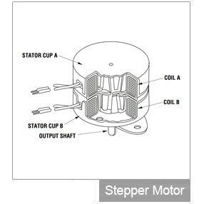
There are three basic types of step motors: variable reluctance, permanent magnet, and hybrid. This discussion will concentrate on the hybrid motor, since these step motors combine the best characteristics of the variable reluctance and permanent magnet motors. They are constructed with multi-toothed stator poles and a permanent magnet rotor. Standard hybrid motors have 200 rotor teeth and rotate at 1.8º step angles. Because they exhibit high static and dynamic torque and run at very high step rates, hybrid step motors are used in a wide variety of commercial applications including computer disk drives, printers/plotters, and CD players. Some industrial and scientific applications of stepper motors include robotics, machine tools, pick and place machines, automated wire cutting and wire bonding machines, and even precise fluid control devices.
Step Modes
Stepper motor "step modes" include Full, Half and Microstep. The type of step mode output of any stepper motor is dependent on the design of the driver. Omegamation™ offers stepper motor drives with switch selectable full and half step modes, as well as microstepping drives with either switch-selectable or software-selectable resolutions.
FULL STEP
Standard hybrid stepping motors have 200 rotor teeth, or 200 full steps per revolution of the motor shaft. Dividing the 200 steps into the 360° of rotation equals a 1.8° full step angle. Normally, full step mode is achieved by energizing both windings while reversing the current alternately. Essentially one digital pulse from the driver is equivalent to one step.
HALF STEP
Half step simply means that the step motor is rotating at 400 steps per revolution. In this mode, one winding is energized and then two windings are energized alternately, causing the rotor to rotate at half the distance, or 0.9°. Although it provides approximately 30% less torque, half-step mode produces a smoother motion than full-step mode.
MICROSTE
Microstepping is a relatively new stepper motor technology that controls the current in the motor winding to a degree that further subdivides the number of positions between poles. Omegamation microstepping drives are capable of dividing a full step (1.8°) into 256 microsteps, resulting in 51,200 steps per revolution (.007°/step). Microstepping is typically used in applications that require accurate positioning and smoother motion over a wide range of speeds. Like the half-step mode, microstepping provides approximately 30% less torque than full-step mode.
Linear Motion Control
The rotary motion of a stepper motor can be converted to linear motion using a lead screw/worm gear drive system (See figure B). The lead, or pitch, of the lead screw is the linear distance traveled for one revolution of the screw. If the lead is equal to one inch per revolution, and there are 200 full steps per revolution, then the resolution of the lead screw system is 0.005 inches per step. Even finer resolution is possible by using the step motor/drive system in microstepping mode.
Series vs. Parallel Connection
There are two ways to connect a stepper motor, in series or in parallel. A series connection provides a high inductance and therefore greater torque at low speeds. A parallel connection will lower the inductance which results in increased torque at faster speeds.
Driver Technology Overview
The stepper motor driver receives step and direction signals from the indexer or control system and converts them into electrical signals to run the step motor. One pulse is required for every step of the motor shaft. In full step mode, with a standard 200-step motor, 200 step pulses are required to complete one revolution. The speed of rotation is directly proportional to the pulse frequency. Some drivers have an on-board oscillator which allows the use of an external analog signal or joystick to set the motor speed.
Speed and torque performance of the step motor is based on the flow of current from the driver to the motor winding. The factor that inhibits the flow, or limits the time it takes for the current to energize the winding, is known as inductance. The effects of inductance, most types of driver circuits are designed to supply a greater amount of voltage than the motor's rated voltage. The higher the output voltage from the driver, the higher the level of torque vs. speed. Generally, the driver output voltage (bus voltage) should be rated at 5 to 20 times higher than the motor voltage rating. In order to protect the motor from being damaged, the step motor drive should be current-limited to the step motor current rating.
Indexer Overview
The indexer, or controller, provides step and direction outputs to the driver. Most applications require that the indexer manage other control functions as well, including acceleration, deceleration, steps per second and distance. The indexer can also interface to and control many other external signals.
Communication to the indexer is through an RS-232 serial port and in some cases an RS485 port. In either case, the indexer is capable of receiving high-level commands from a host computer and generating the necessary step and direction pulses to the driver.
The indexer includes auxiliary I/O for monitoring inputs from external sources such as a Go, Jog, Home or Limit switch. It can also initiate other machine functions through the I/O output pins.
Stand-Alone Operation
In a stand-alone mode the indexer can operate independent of the host computer. Once downloaded to the non-volatile memory, motion programs can be initiated from various types of operator interfaces, such as a keypad or touchscreen, or from a switch through the auxiliary I/O inputs. A stand-alone stepper motor control system is often packaged with a driver and power supply and optional encoder feedback for "closed loop" applications that require stall detection and exact motor position compensation.
Multi-Axis Control
Many motion applications have more than one stepper motor to control. In such cases a multi-axis control system is available. A HUB 444 networking hub, for example, may have up to four stepper drives connected to it, with each drive connected to a separate stepper motor. The networking hub provides coordinated movement for applications requiring a high degree of synchronization, such as circular or linear interpolation.
Choosing a Stepper Motor and Drive
The choice of a step motor depends on the application's torque and speed requirements. Use the motor's torque-speed curve (found in each drive's specifications, example in figure C) to select a motor that will do the job. Every stepper drive in the Omegamation line shows the torque-speed curves for that drive's recommended motors. If your torque and speed requirements can be met by multiple step motors, choose a drive based upon the needs of your motion system- step/direction, stand-alone programmable, analog inputs, microstepping- then choose one of the recommended motors for that drive. The recommended motor list is based on extensive testing by the manufacturer to ensure optimal performance of the step motor and drive combination.
 Step and Direction
 Oscillator
 Stand-Alone Programmable
 High Performance Stepper Motors

 Motores de Passo
 Moteurs pas à pas
 Stepper Motors
 Moteur pas à pas
 Schrittmotoren
 Stepper Motor
 Stepper Motor
 Stepper Motors
 Stepper Motors
 스테퍼 모터
 Stepper Motors
 Stepper Motors
 Stepper Motors
 Stepper Motors
 Stepper Motors